Thursday, January 31, 2008

Process of DVD Recording
Menu: Project - Burn DVD from diskThis is the last step in the DVD creation process.With our DVD Project having been Compiled, there are a set of files that DVD-lab has prepared for you in the Output folder as set in the Compile process. At this point, the DVD Author has choices as to how to convert this set of files into a DVD master disc. You can either use the DVD-lab built-in recording module or you can choose to use a third party DVD recording software such as Nero, Prassi, Gear, etc...

It is common that you are supplied with a DVD recording software that was bundled with your DVD-R/DVD+R burner. This software may be better optimized for your particular drive. The DVD-lab built-in DVD recording module is a general ASPI writing application and should work fine. In an ideal world, either one would work equally well.


DVD-lab Disc record window


The DVD-lab Disc record window is automatically detached. That means it runs as a separate process independent from DVD-lab, you could even close DVD-lab and the recording will continue.
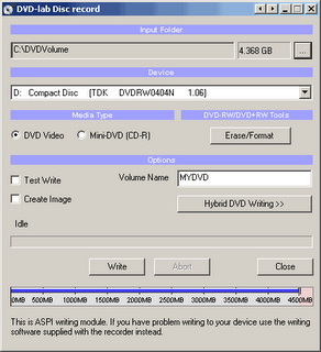


Input Folder


The Input Folder is the same as the Output folder in Compile. That means this is the folder where the VIDEO_TS and AUDIO_TS folders are expected to be.


Device


The DVD recording drive you want to write to, presented as the O/S recognizes it.


Media Type


Set if you want to burn DVD Video or a Mini-DVD.


Mini-DVD

is a DVD format burned on the CD-R. Obviously you can put far less data on a CD-R (about 700 MB) than on DVD (4.3 GB)


The size indicator on the bottom can help you to determine how much data you can record to the disc. You have to keep your data below the red area.


DVD-RW/DVD+RW Tool

For those using a re-writable media, the DVD-RW needs to be formatted if they were already used - click the Erase/Format button to do this. The more common DVD-R media do not need any formatting.
The DVD-RW and +RW needs to be finalized after writing. This takes quite a large amount of time on RW media. Please be patient until this important process is completed.


Options:
Test Write checkbox
Use this option by checking the Test Write checkbox to have DVD-lab do a trial run at writing a DVD. This option does not write anything to disk or your hard drive, it merely goes through the motions to insure that all of the content and menus within the DVD project are correctly prepared and defined.
Create Image checkbox
You can choose to have DVD-lab create a large file on your hard drive which is an the image of a DVD disc instead of burning. The result will be one big IMG file. That IMG file can be used with a number of third party DVD recording software to replicate a DVD disc from this image file, as many times as you like, whenever you like. Some software will look for a ISO file name extension, if so, just rename the file to a .ISO extension. This method has the advantage of speed as the DVD image is all prepared on your hard drive, it is then a just matter of how fast your DVD burner drive will burn that image.
Hybrid DVD Writing button
You can add additional files and folders to the DVD master disc with the Hybrid DVD Writing option. What this option will do is setup an alternate filesystem on the DVD master disc which is called an ISO filesystem. The ISO format is what a standard CD uses while the DVD video is in UDF/ISO. This is perfectly DVD "legal" as the DVD player doesn't know or care about this ISO filesystem's contents, it just looks for a UDF filesystem.
It doesn't matter at all what the content or nature of these files are. They are just files, not Windows or Mac or Linux files, just files. As they are recorded into the ISO file system domain, they are available on any computer with a DVD drive. This offers the DVD-lab Author some creative options for bonus content that would be available to a computer user on any O/S that supports a DVD drive.

Thursday, January 24, 2008

CPU Socket
A CPU socket or CPU slot is a connector on a computer's motherboard that accepts a CPU and forms an electrical interface with it. As of 2007, most desktop and server computers, particularly those based on the Intel x86 architecture, include socketed processors.
Most CPU-sockets interfaces are based on the pin grid array (PGA) architecture, in which short, stiff pins on the underside of the processor package mate with holes in the socket. To minimize the risk of bent pins, zero insertion force (ZIF) sockets allow the processor to be inserted without any resistance, then grip the pins firmly to ensure a reliable contact after a lever is flipped.
As of 2007, several current and upcoming socket designs use land grid array (LGA) technology instead. In this design, it is the socket which contains pins. The pins contact pads or lands on the bottom of the processor package.
In the late 1990s, many x86 processors fit into slots, rather than sockets. CPU slots are single-edged connectors similar to expansion slots, into which a PCB holding a processor is inserted. Slotted CPU packages offered two advantages: L2 cache memory could be upgraded by installing an additional chip onto the processor PCB, and processor insertion and removal was often easier. However, slotted packages require longer traces between the CPU and chipset, and therefore became unsuitable as clock speeds passed 500 MHz. Slots were abandoned with the introduction of AMD's Socket A and Intel's Socket 370.

Wednesday, January 23, 2008

CPU Package Types

PPGA Package


PPGA is short for Plastic Pin Grid Array, and these processors have pins that are inserted into a socket. To improve thermal conductivity, the PPGA uses a nickel plated copper heat slug on top of the processor. The pins on the bottom of the chip are staggered. In addition, the pins are arranged in a way that the processor can only be inserted one way into the socket. The PPGA package is used by early Intel Celeron processors, which have 370 pins.

PGA package


PGA is short for Pin Grid Array, and these processors have pins that are inserted into a socket. To improve thermal conductivity, the PGA uses a nickel plated copper heat slug on top of the processor. The pins on the bottom of the chip are staggered. In addition, the pins are arranged in a way that the processor can only be inserted one way into the socket. The PGA package is used by the Intel Xeon™ processor, which has 603 pins

S.E.C.C 2 package


The S.E.C.C.2 package is similar to the S.E.C.C. package except the S.E.C.C.2 uses less casing and does not include the thermal plate. The S.E.C.C.2 package was used in some later versions of the Pentium II processor and Pentium III processor (242 contacts).

S.E.P package


S.E.P. is short for Single Edge Processor. The S.E.P. package is similar to a S.E.C.C. or S.E.C.C.2 package but it has no covering. In addition, the substrate (circuit board) is visible from the bottom side. The S.E.P. package was used by early Intel Celeron processors, which have 242 contacts.

S.E.C.C package


S.E.C.C. is short for Single Edge Contact Cartridge. To connect to the motherboard, the processor is inserted into a slot. Instead of having pins, it uses goldfinger contacts, which the processor uses to carry its signals back and forth. The S.E.C.C. is covered with a metal shell that covers the top of the entire cartridge assembly. The back of the cartridge is a thermal plate that acts as a heatsink. Inside the S.E.C.C., most processors have a printed circuit board called the substrate that links together the processor, the L2 cache and the bus termination circuits. The S.E.C.C. package was used in the Intel Pentium II processors, which have 242 contacts and the Pentium® II Xeon™ and Pentium III Xeon processors, which have 330 contacts.

Thursday, January 17, 2008

Form Factors of Motherboard

LPX


White ATX is the most well-known and used form factor, there is also a non-standard proprietary form factor which falls under the name of LPX, and Mini-LPX. The LPX form factor is found in low-profile cases (desktop model as opposed to a tower or mini-tower) with a riser card arrangement for expansion cards where expansion boards run parallel to the motherboard. While this allows for smaller cases it also limits the number of expansion slots available. Most LPX motherboards have sound and video integrated onto the motherboard. While this can make for a low-cost and space saving product they are generally difficult to repair due to a lack of space and overall non-standardization. The LPX form factor is not suited to upgrading and offer poor cooling.

BTX


The BTX, or Balanced Technology Extended form factor, unlike its predecessors is not an evolution of a previous form factor but a total break away from the popular and dominating ATX form factor. BTX was developed to take advantage of technologies such as Serial ATA, USB 2.0, and PCI Express. Changes to the layout with the BTX form factor include better component placement for back panel I/O controllers and it is smaller than microATX systems. The BTX form factor provides the industry push to tower size systems with an increased number of system slots.
One of the most talked about features of the BTX form factor is that it uses in-line airflow. In the BTX form factor the memory slots and expansion slots have switched places, allowing the main components (processor, chipset, and graphics controller) to use the same airflow which reduces the number of fans needed in the system; thereby reducing noise. To assist in noise reduction BTX system level acoustics have been improved by a reduced air turbulence within the in-line airflow system.
Initially there will be three motherboards offered in BTX form factor. The first, picoBTX will offer four mounting holes and one expansion slot, while microBTX will hold seven mounting holes and four expansion slots, and lastly, regularBTX will offer 10 mounting holes and seven expansion slots. The new BTX form factor design is incompatible with ATX, with the exception of being able to use an ATX power supply with BTX boards.
Today the industry accepts the ATX form factor as the standard, however legacy AT systems are still widely in use. Since the BTX form factor design is incompatible with ATX, only time will tell if it will overtake ATX as the industry standard.

ATX


With the need for a more integrated form factor which defined standard locations for the keyboard, mouse, I/O, and video connectors, in the mid 1990's the ATX form factor was introduced. The ATX form factor brought about many chances in the computer. Since the expansion slots were put onto separate riser cards that plugged into the motherboard, the overall size of the computer and its case was reduced. The ATX form factor specified changes to the motherboard, along with the case and power supply. Some of the design specification improvements of the ATX form factor included a single 20-pin connector for the power supply, a power supply to blow air into the case instead of out for better air flow, less overlap between the motherboard and drive bays, and integrated I/O Port connectors soldered directly onto the motherboard. The ATX form factor was an overall better design for upgrading.

NLX


Boards based on the NLX form factor hit the market in the late 1990's. This "updated LPX" form factor offered support for larger memory modules, tower cases, AGP video support and reduced cable length. In addition, motherboards are easier to remove. The NLX form factor, unlike LPX is an actual standard which means there is more component options for upgrading and repair.
Many systems that were formerly designed to fit the LPX form factor are moving over to NLX. The NLX form factor is well-suited to mass-market retail PCs.